FICS Fusion Experiment

Hang up the labcoat, relax and chat about anything
User avatar
Sesselmann
Posts: 1168
Joined: 27 Apr 2015, 11:40
Location: Sydney
Contact:

FICS Fusion Experiment

Post by Sesselmann » 06 Jan 2016, 10:12

Some of you may be interested in my current project, I am building a particle collider or a fusor. It's not the first one, I have built three versions before this one, after building each one I realised how I could make improvements, so I built another one, so here is number four.

It is a high vacuum system with a linear accelerator tube having a low negative electrical potential on the cathode, molecules of Deuterium are ionised in the cathode, where some undergo fusion, releasing a neutron, an alpha particle and around 3.7 meV of excess energy. My projects always have some new elements which require R&D so I expect it will take up to one year to complete. I have made a good start over the Christmas break, but this initial work pictured below was simple brainless work and progressed fairly fast.

Providing I manage to get this apparatus to operate in a steady state mode, It should be able to produce neutrons on demand, which may enable some activation experiments, but neutrons are not the primary objective of the experiment, I am hoping to demonstrate a system of Fusion Induced Charge Separation, which is why I have called the experiment for F.I.C.S.

When a fusion reaction takes place a charged alpha particle is ejected with lots of kinetic energy, so when this takes place inside the cathode, the positively charged particle is shot up through the accelerator tube against the charge gradient, thereby leaving the cathode with another negative charge, using a system of diodes it should be possible to close the circuit and measure the fusion induced charge separation, well thats the plan anyway.

I shall post more as I make progress..

Steel frame construction welded from 30x30mm steel tube.
FICS- - 2.jpg (96.68 KiB) Viewed 16817 times
Finished steel frame with castors
FICS- - 3.jpg (124.98 KiB) Viewed 16817 times
Faraday cage and vacuum fore pump fitted, turbo pump alignment in progress
FICS- - 4.jpg (193.2 KiB) Viewed 16817 times
Two stage vacuum pump and Glassman high voltage supply
FICS- - 1.jpg (139.91 KiB) Viewed 16817 times
Concept drawing of flight tube
fics.jpg (34.04 KiB) Viewed 16817 times
Concept drawing of flight tube.
flight tube 2.jpg (37.08 KiB) Viewed 16817 times

User avatar
Geoff
Posts: 140
Joined: 01 May 2015, 12:21
Location: Marathon County, Wisconsin
Contact:

Re: FICS Fusion Experiment

Post by Geoff » 06 Jan 2016, 15:32

Very exciting! I know I'll be following along on your project. Definitely beyond my ability level.
Geoff Van Horn

Former Alaskan living in rural Wisconsin

User avatar
Sesselmann
Posts: 1168
Joined: 27 Apr 2015, 11:40
Location: Sydney
Contact:

Re: FICS Fusion Experiment

Post by Sesselmann » 14 Feb 2016, 10:01

Hi Guys,

Just a 6 minute progress report on my project, work, family and life in general means it's progressing slowly, but at least it's moving forward.


https://youtu.be/nwG_y3ZFV9g
Progress report
Progress report
progress-video.png (120.98 KiB) Viewed 16759 times

Steven

User avatar
Sesselmann
Posts: 1168
Joined: 27 Apr 2015, 11:40
Location: Sydney
Contact:

Re: FICS Fusion Experiment

Post by Sesselmann » 23 Jul 2016, 15:10

Hi Guys,

It has been a while since I posted news about my FICS fusion experiment, well that doesn't mean I'm not working on it, the fact is I have been making good progress. We now have vacuum, a major milestone for any fusioneer, not only vacuum but good vacuum with an acceptably low leak rate (harder to achieve than many realise).

People thought I was either crazy or ignorant when I told them I was going to glue my vacuum chamber together with Latex carpet glue, but with the right preparation natural latex forms a hermetic seal with minimal outgassing and is flexible enough to allow for thermal expansion between aluminium and glass.

Preparation of the glass and aluminium is the key to success, so with 50 micron aluminium oxide powder and water, I ground the two surfaces together until they were evenly smooth all over, with a matt active surface, I then rinsed the discs thoroughly in clean water followed by deionised water, before drying and gluing.

Well it's all together now and holding vacuum, so to all you skeptics out there, it works!

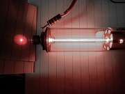
Here is the rig how it looks today, we are almost there...
FICS Fusion rig
FICS Fusion rig
160723 - 1.jpg (179.91 KiB) Viewed 15978 times
This is the high voltage double ended accelerator, where you can clearly see how it has been glued together. I have a system of four turnbuckles to maintain a good tension on the stack at all times and hold it firmly so it doesn't move in the cage. The two ends are maintained at ground potential at all times. The high voltage bias is connected with the two red cables to disc 9 and 11 either side of the reaction chamber, and the reaction chamber is connected via a 400V Zener diode and the yellow cable, this arrangement is for electron suppression, so when we burn a fusion plasma in the chamber we prevent electrons escaping up the tubes, which is the primary source of energy loss in fusors.
Double ended accelerator
160723 - 2.jpg (199.71 KiB) Viewed 15978 times
On the next picture we can see the gas inlet into the reaction chamber, this is another one of my own inventions, because I don't believe (and I think I am the only one) in a Coulomb force, because there isn't one, I will prove that soon. Feeding neutral gas into a low potential plasma generates slow ions, and my objective is to make them stand still, this is contrary to all other fusion efforts where scientists believe they need a high temperature plasma to overcome the imaginary "Coulomb" force.
Fusion chamber wiring
160723 - 3.jpg (130.38 KiB) Viewed 15978 times
Controlling the gas flow into the chamber at low potential turned out to be tricky, I had to develop a whole battery powered system floating at -50,000V with fibre optic data connection. I'm still developing this part of the project.
FICS Pressure controller
160723 - 4.jpg (180.4 KiB) Viewed 15978 times
This is the main source of power, it's a Spellman 125 kV lab supply and can be (will be) controlled remotely from labView. These units are not cheap, but I got it on eBay with a minor fault and fixed it.
125 kV Glassman power supply
160723 - 5.jpg (57.46 KiB) Viewed 15978 times
The following image shows the fore vacuum system, which consists of a two stage rotary vane pump and a stainless steel tank. The tank isn't essential, but it is a safety reservoir in case the rotary fails (prevents killing the turbo).
Fore vacuum pump
Fore vacuum pump
160723 - 6.jpg (55.46 KiB) Viewed 15978 times
The next picture is the DAQ (Data Acquisition Module), here I am using four analog inputs and two analog outputs. These connections allow me to control power supply and monitor the actual consumption current remotely with LabView.
NI-6008 Data acquisition module
160723 - 7.jpg (53.05 KiB) Viewed 15978 times
Following is my deuterium cylinder, it is bigger than a typical lecture bottle and inconvenient to float at high potential so I have made a system of valves and connections which allow me to pull a vacuum in a small sample cylinder and decant a small amount of deuterium into the sample cylinder. Very little is needed to run the reactor.
Deuterium decanting system
160723 - 8.jpg (82.16 KiB) Viewed 15978 times
next up is the Varian V200 turbo pump, this one has given me a bit of a headache lately as it became hot, causing the grease to run out of the bearing and cease up, so I had to pull it apart and fix it, it was a big job, but now working fine.
Varian V200 turbo pump
160723 - 9.jpg (53.9 KiB) Viewed 15978 times
Here you can see how the vacuum system is connected to the stack with NW25 fittings, for the absolute vacuum purist NW25 fittings are not the thing to use for ultra high vacuum, but it's a trade off between convenience and perfection. I am not a purist I just want to run this experiment and achieve an outcome. My current leak rate in this total volume of around 5 litres is 1 micron every 10 seconds and the turbo pump easily copes with that.
Vacuum Connections to end caps
160723 - 10.jpg (71.66 KiB) Viewed 15978 times
So that where I am up now...

Still to do is finishing the remote control of the gas handling system and then I will be ready to learn how to drive this monster.

As a pioneer in FICS fusion I am building a machine that no-one including myself knows how to drive, so it's a matter of figuring it out, I guess the Wright brothers had the same problem, they built the first aeroplane but non of them knew how to fly ;)

Steven

User avatar
Sesselmann
Posts: 1168
Joined: 27 Apr 2015, 11:40
Location: Sydney
Contact:

Re: FICS Fusion Experiment

Post by Sesselmann » 23 Jul 2016, 16:59

Here is the front end of the Labview VI (Virtual Instrument) I'm developing.

For safety reasons and for the purpose of logging the experimental data I am using a Labview data acquisition system. With Labview I can remotely operate the experiment from a safe distance and apply various programming loops to maintain stability of the system.

The four virtual slide potentiometers (bottom centre) are my set controls;
  • Voltage
  • Current
  • Chamber pressure
  • gas flow rate
The meter panels on the left are actual volts out and actual current. The meters on the right from the top are, Vacuum gauge between turbo pump and accelerator stock, vacuum gauge for actual reaction chamber, and bottom meter is for F.I.C.S (Fusion Induced Charge Separation) which is what this experiment is all about.

The big meter top centre and the graph shows differential current, current in less FICS current, so in simple terms if it swings to the right its using power and if it swings to the left it's generating power.

Colourful isn't it :)
Labview VI
Labview VI
Vi2.PNG (143.95 KiB) Viewed 15963 times


User avatar
Sesselmann
Posts: 1168
Joined: 27 Apr 2015, 11:40
Location: Sydney
Contact:

Re: FICS Fusion Experiment

Post by Sesselmann » 23 Apr 2017, 21:21

Hi Guys,

Here is an update on my fusion project. In my last report (the video) I was pretty negative about the experiment, I had spent six months on complicated electronics and fibre optic control of the floating gas supply system, and it hadn't worked, so I gave the project a rest for a few weeks and pondered about solutions to the problem, and in or around middle of January I had and idea...

If I could invent a way to prevent plasma from ionising inside the gas line between the cathode and ground, I wouldn't have to float the gas cylinder and the pressure controller, and the whole apparatus would be so much simpler, but how?

The trick is to prevent electrons from travelling through the gas to ground (like in a neon tube) so I was thinking about some kind of plastic pump, when the idea struck me that I might be able to use a glass airlock, similar to the kind used by wine makers to keep air out of the brew.

Obviously water wouldn't work in a vacuum, but what about diffusion pump oil, it's designed to be in a high vacuum and has extremely low vapour pressure. Surely this would work, so I jokingly called it the "flux capacitor" as in Back to the Future.
Flux Capacitor (without oil)
flux-capacitor - 1.jpg (75.41 KiB) Viewed 14921 times
I had one made up by the local glass blower and it looked promising, but at 25-30 kV the plasma worked its way through the oil and flashed back to ground, so I had to get a bigger one made so it would hold a larger column of oil.

So last week I tested the longer version and managed to get a good 45 minute run before the plasma broke through the side wall of the thin walled glass tube.

Here is the run data from the 45 minute run. As you can see it took around 15 minutes before I started seeing neutrons, but then the counts started rising steadily. At one point the TIER (Total Isotropic Emission Rate) spiked at 400,000 n/s. At that point something went wrong and when I went to check on the experiment I noticed tiny bubbles in the flux capacitor, which on closer inspection turned out to be a hole in the glass tube. My guess is that the high voltage plasma had burned through the glass at that point.
19th. April 2017
19th. April 2017
FICS-Run-2017-04-19.PNG (105.86 KiB) Viewed 14921 times
This has given me the confidence to continue down this road, so I have ordered a new flux capacitor, this time with thick walled tubing, which should allow me to go over the 50 kV threshold which is what I need for the experiment.

After last weeks run I am pretty confident I can hit the 1 million n/s mark.

Steven

PS: For the neutron detection I used my GS-Neutron-150 directly connected to my PC sound card, the pulses are read directly in Labview where I have written a virtual rate meter program.
Labview Acquire
Labview Acquire
labview.jpg (30.52 KiB) Viewed 14919 times

lodovico
Posts: 64
Joined: 10 May 2015, 23:08
Contact:

Re: FICS Fusion Experiment

Post by lodovico » 05 May 2017, 23:44

WOW !

Boris
Posts: 36
Joined: 27 Apr 2015, 23:33
Contact:

Re: FICS Fusion Experiment

Post by Boris » 11 May 2017, 04:36

Steven, what a big experiment amazing.

Its way to complicated for me, but inspired by your work some thoughts flash through my head:
You could submerge the Glass "flux capacitor" in dielectric oil in a aquarium, for cooling (add a small pump and radiator, but that is just overkill).
The oil we use in the Hv tank (truck battery size HV capacitor) of xray systems goes all the way op to 150 Kv, with some safety margin.
And I was wondering what the effect would be if you did not use a "real" ground, control the voltage but when the current goes up and conductivity is starting to happen, you make the resistance to ground higher, with some feedback system.

Cheers, Boris

Boris
Posts: 36
Joined: 27 Apr 2015, 23:33
Contact:

Re: FICS Fusion Experiment

Post by Boris » 11 May 2017, 05:16

and some more pops in my mind...

if you use 2 power supplies, with both grounds connected to a central electrode and left and right the negative electrodes both electron beams would be opposite to each other improving the chance of collision, injecting the deuterium from both sides

=======> 0 <=======
-50 Kv gnd -50Kv

the electrodes could be a needle injecting the deuterium , the central ground electrode a washer shape ring, allowing the collisions to happen in the center.
maybe a electromagnet around the beams is needed to shape and focus the beams.(just as in old tube tv´s)

Regards, Boris.

Post Reply

Who is online

Users browsing this forum: No registered users and 1 guest