
They can be used for general purpose counting, spectroscopy for many kinds of particles and energy ranges, as well as dosimetry and are only slowly replaced by scintillators and semiconductors.
Proportional Detectors are a subset of gaseous detectors, introducing gas gain to the equation and amplifying pulses to make it easier to detect them. Their most common form is a cylindrical arrangement, consisting of an outer tube used as cathode, and a thin anode wire tensioned down the middle. Applying a high positive voltage to the anode results in an electrical field inside the tube that is proportional to 1/r.
When radiation enters the detector it will ionize the gas inside, the electrical field accelerates positive ions to the cathode and electrons to the anode. Due to the gradient in the field the electrons gain more and more kinetic energy until they can ionize more gas, creating more free electrons and setting off an avalanche, resulting in a sizeable, measurable current.
This avalanche is called the gas multiplication factor, or gas gain, and ideally it is constant, regardless of the number of ion-electron pairs that set it off. That way the resulting output signal just depends on the number of ionisations in the primary event, which often gives information about the energy deposited in the gas.
This gas gain is dependant on a few factors. The applied anode voltage of course determines the magnitude of the electrical field, just like the diameters of the anode and cathode.
The gas itself also strongly influences the gain, because in different gasses the electrons need different energies to cause further ionisations. The pressure determines both the stopping power of your gas filling, as well as how far electrons can travel before hitting another neutral atom, further influencing the gain.
All the factors have to be carefully dialed in to get a detector with just the properties you want.
Cathode diameter determines your detectors actual size, your gas and its pressure determines how it reacts to what kind of radiaion, and the applied voltage can’t be arbitrarily high.
In this article I will demonstrate a cheap and simple way to manufacture a “general purpose” proportional counter. This detector is not very useful on its own, but a good base to build on for the development of different kinds of detectors.
The cathode of my detector is a 28 mm diameter copper tubing with 1 mm wall thickness. This will block a lot of lower energy x-rays / gammas, as well as pretty much all alphas and betas. But eg. neutrons would be let through easily, so with the right gas filling this would make a decent neutron detector.
For evacuating and filling I brazed a copper capillary from a fridge to it, and afterwards cleaned it in a hot citric acid solution.
- photo_2021-05-02_23-24-14.jpg (38.87 KiB) Viewed 862 times
They must not let any gas in or out, don’t outgas too much, and isolate the anode voltage against the cathode. Since we’re talking about very small signals it also is a big plus if the feedthrough is coaxial, in order to have the cathode as electrical shield.
Since most proportional detectors work at, or close to, atmospheric pressure leak rate or diffusion through the feedthroughs can be ignored in many cases. A metal to ceramic or glass seal would be ideal, but that is hard to do at home and often unreliable if not done by an expert.
A cheap method I have found to be adequate are printed circuit boards. FR-4 is made of glass fiber and Epoxy, both materials well suited for clean and low pressure applications. Thanks to a huge selection of manufacturers they can be ordered for cheap from china, and a soldered THT connection is absolutely leak tight.
As a feedthrough and connector in one I used a BNC print connector, with the anode wire directly soldered to its center pin. The other end of the cathode is sealed with the same PCB, but without a connector and only the holes soldered shut.
- The cleaned tube with its end PCBs
- photo_2021-05-02_23-24-55.jpg (21.96 KiB) Viewed 862 times
Both PCBs were soldered onto the copper tube with electrical solder. First the PCB with the connector and anode wire, then the other one, making sure to thread the anode through its center hole before soldering it to the tube. After both PCBs were firmly connected to the tube I turned it so that the connector side was facing up, applied a small weight of around 100 g to the wire and soldered to the PCB under tension. This sealed the detector and only left the fill tube as a connection to the outside.
Now comes the fun part of evacuating, flushing and filling the detector. As fill gas I am using Ar/CO2 82/18, because it has good overall properties and can be bought cheap as a welding gas.
For evacuating I used a molecular drag pump, backed by a rotary vane. Chosing a pump that can be vented to atmosphere greatly reduced the time needed for a flush, and made everything safer in general. The counter tube was connected to a cross, together with a pirani pressure gauge, a valve to the pumps and a needle valve to my gas cylinder.
- photo_2021-05-02_23-25-44.jpg (54.44 KiB) Viewed 862 times
If you go with the “flushing method” I have found that, of course depending on the size of your detector, 5-10 flushes are needed to get it working well.
After you’ve made sure you have no oxygen in your system you have to refill it to a certain pressure again. If you know what pressure you need that’s easy, but I wanted to have it count well at a certain voltage. So I set my ratemeter, a Ludlum Model 12, to the desired 1900V, closed the valve to the pumps and slowly let in Ar/CO2. At first the ratemeter will scream like all hell is breaking loose, but with rising pressure the count rate will drop. Those counts are just gas discharges happening inside the detector, at this point is is basically a gas discharge lamp. When the counts drop off quickly you have reached the lower end of your working pressure range.
Bring a check source near your detector and watch it count!
If it doesn’t you either have some oxygen left in the detector, or you overshot the pressure range. In either case you can just pump it back down and refill it again. Raising the pressure above this lower end will lower the gas gain.
If you are happy with how it works you now need to seal off the detector. Thanks to the heat involved in brazing the capillary the copper was already really soft. I pinched it closed with ~3 mm pliers, and then cut it off with dull side cutters, which have the advantage of pressing the tube more instead of just cutting it. This already seals the detector well, but I tend put a drop of solder on the cut surface, just to make sure it is absolutely closed.
- photo_2021-05-02_23-26-23.jpg (27.93 KiB) Viewed 862 times
The way I have built it it is not very useful. It only reacts to x-rays / gammas above ~50 keV and not much more. It doesn’t come close to stopping the photons completly, so it can’t be used for spectroscopy either. It just counts, similar to a geiger counter. It is a nice demonstration piece, but not much more.
Here's a small video of the counter in action:
https://www.youtube.com/watch?v=3Hbj9gbc8nk
Since the gain is exponentially dependant on the voltage an easy way to test proportional counters is to sweep their voltage and record the resulting count rate. Triggering a count above a certain charge per event will result in an exponential increase in the count rate, as more and more detection events go above the detection threshold, until it tapers off to a flat line, when every event inside the detector is being counted. Further increase of the anode voltage will not increase the count rate, but only the events amplitude, until the detector leaves the area of proportionality and turns into a Geiger Müller counter. Above even that the count rate will increase again, as high voltage breakdowns occur inside the detector.
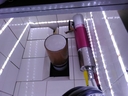
For the characterisation of this detector I built a small lead castle to exclude background events, and used a ²²⁶Ra check source, shielded behind 1.25 mm of lead to cut out the low end of the spectrum.
I later discovered that the detector does not noticably react to 508 keV gammas, so the shaping of the spectrum probably was not neccesary. The way the castle was built the detector had at least 5 cm of lead in every direction, effectively shielding it from most, if not all outside influences.
- photo_2021-05-02_23-28-02.jpg (18.06 KiB) Viewed 862 times
- photo_2021-05-02_23-28-05.jpg (34.37 KiB) Viewed 862 times
A Canberra 3105D NIM was the high voltage source, and a handheld DMM read the voltage through a 10 GOhm resistor, displaying 1/1000th of the actual value.
- photo_2021-05-02_23-29-26.jpg (43.81 KiB) Viewed 862 times
- photo_2021-05-02_23-30-02.jpg (17.95 KiB) Viewed 862 times
The plateau was reached at a fairly low voltage compared to where the counts actually start rising from zero, which can be explained by the high gain of the 2022. If that was set lower the exponential increase would last for longer and level off at a higher voltage.
While rising the anode voltage to 1700V the frontend FET of my preamplifier died.
I presume this was due to either a Geiger Müller discharge, or a high voltage breakdown inside the detector. From my experiende with this detector on the Model 12 breakdowns don’t occur until at least 300 V higher, so it would be fair to assume that it is reaching into the Geiger Müller region at this point.
It is a good rule of thumb to operate proportional counters ~10% above the voltage where the plateau sets in, so at ~1450V in this example.
Copied and shortened from:
https://gigabecquerel.wordpress.com/202 ... l-counter/
https://gigabecquerel.wordpress.com/202 ... l-counter/
I am looking forward to your questions and recommendations!
Lukas

