
I am working on a proposal to supply a Compton experiment for a University, so I have been teaching myself to use Fusion 360 CAD design software. As always it takes some time to master the various commands of a new software package, but I am slowly getting the hang of it and enjoying it (although the red SHV cable was tricky).
This experiment shines a collimated Cs-137 beam onto a BC412 plastic scintillation detector, and uses a NaI(Tl) or Csi(Tl) detector to record a spectrum of the scattered photons. The objective of the experiment is to show that the resulting energy peak from scattered photons (after colliding with an electron) are predictable and follows a given equation.
To achieve better resolution this experiment uses PRA with two detectors in coincidence mode, but it still takes 10-15 minutes before you see a good peak.
Anyone interested in trying this experiment or having one of these built can PM me above..
Steven
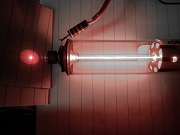
- Design concept for Compton Scatter experiment - close up
- EXP#22(b).jpg (25.22 KiB) Viewed 9223 times
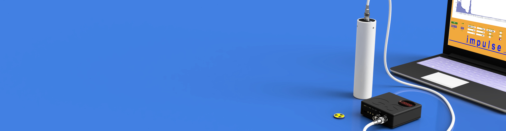
- Design Concept for Compton scatter experiment